Welding Symbols Reference Guide
AWS-compliant welding symbols with practical interpretation examples
Anatomy of a Welding Symbol
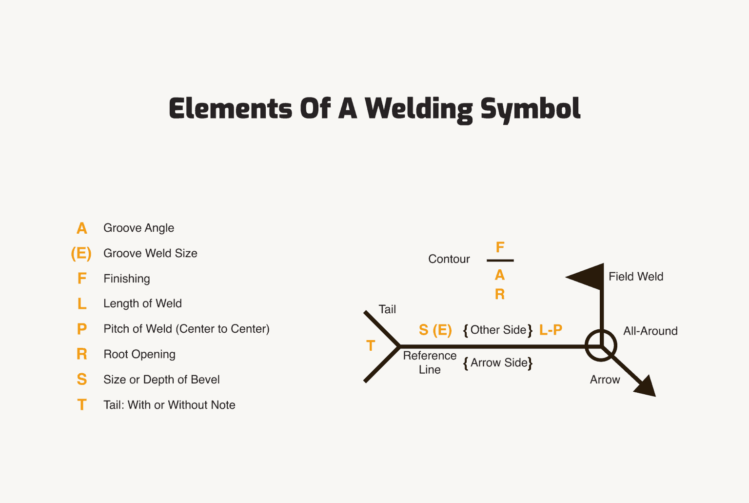
Standard welding symbols consist of several key elements that communicate specific instructions to the welder:
1. Reference Line

The foundation of the welding symbol where all other elements are attached.
2. Arrow
Points to the joint or area to be welded, connecting to the reference line.
3. Tail
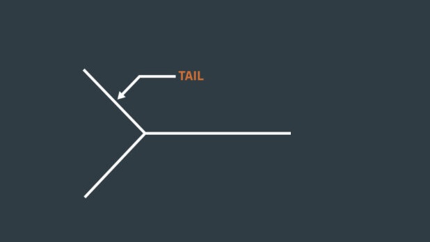
Optional element used to specify the welding process or other reference information.
Basic Weld Symbols
The following table shows the most common weld symbols according to AWS A2.4 standards:
| Symbol | Name | Description | Common Applications |
|---|---|---|---|
|
Fillet Weld | Triangular cross-section joining two surfaces at right angles | T-joints, lap joints, corner joints |
|
Square Groove | Butt joint with square edges | Thin materials, automatic welding |
|
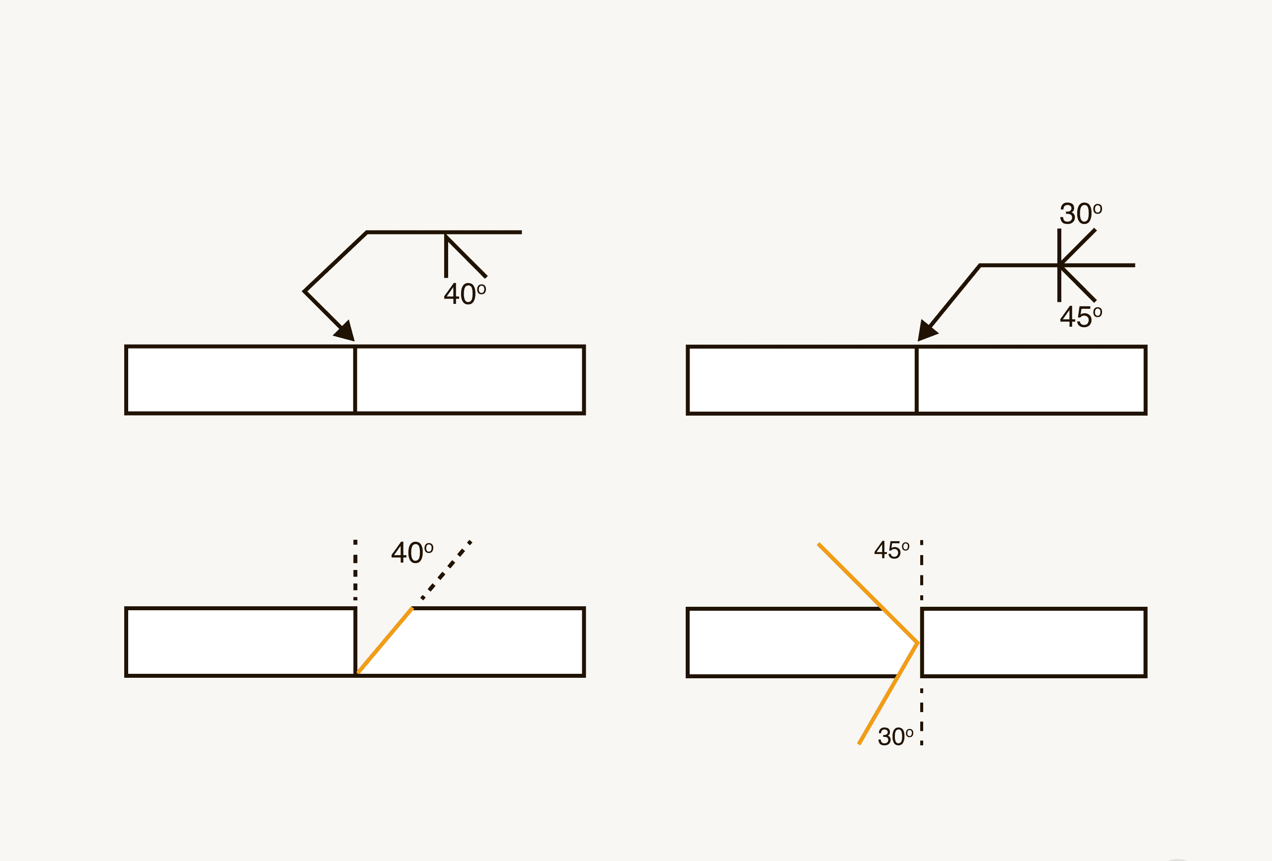
V-Groove | Beveled edges forming a V shape | Thicker materials, single-side preparation |
|
Bevel Groove | One edge beveled, one square | When only one side can be prepared |
|
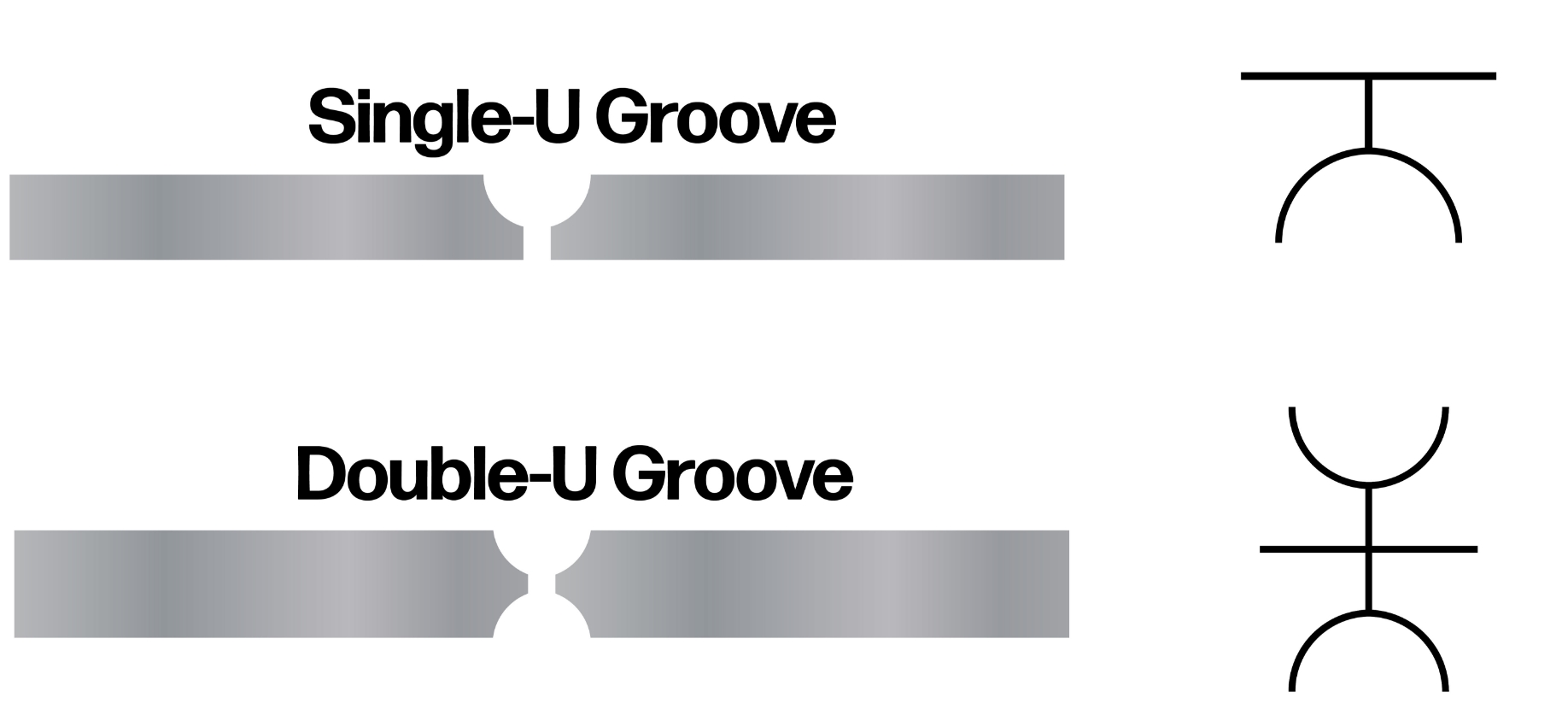
U-Groove | Curved preparation resembling a U | Very thick materials |
|
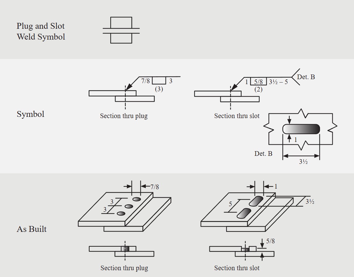
Plug or Slot Weld | Weld made in a hole or slot | Overlapping members where fillet welds aren't sufficient |
Supplementary Symbols
These symbols provide additional information about the weld:
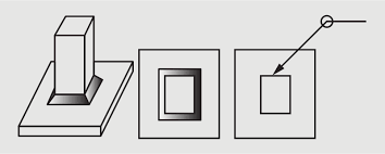
All Around
Weld extends all around the joint
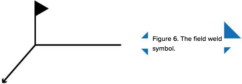
Field Weld
Weld to be made in the field (not in shop)
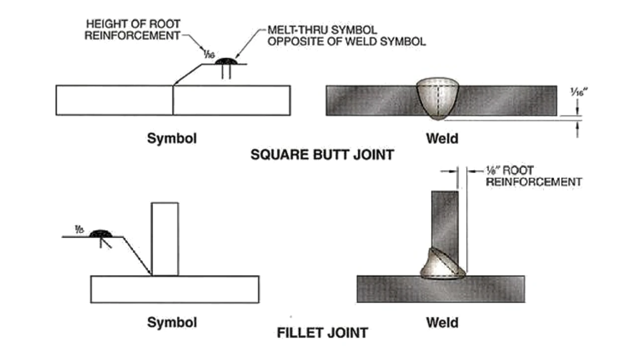
Melt Through
Complete joint penetration required
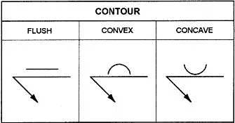
Contour Symbols
Flat, convex, or concave finish specifications
Welding Position Symbols
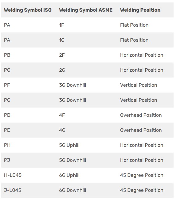
Welding positions are indicated by numbers that follow the weld type:
| Position | Code | Description | Difficulty |
|---|---|---|---|
| Flat | 1 | Weld on upper surface of horizontal plane | Easiest |
| Horizontal | 2 | Weld on vertical surface moving horizontally | Moderate |
| Vertical | 3 | Weld moving vertically up or down | Difficult |
| Overhead | 4 | Weld on underside of horizontal plane | Most Difficult |
Practical Interpretation Examples
Example 1: Simple Fillet Weld
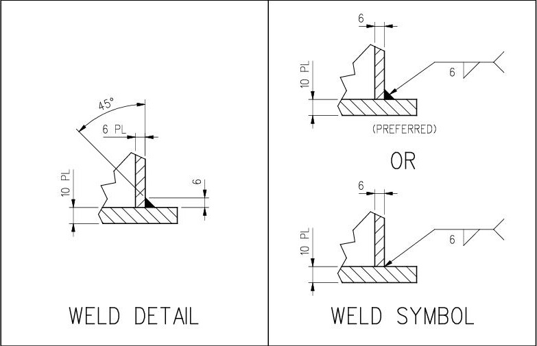
Interpretation: 6mm fillet weld on the arrow side of the joint, with convex contour and no post-weld finishing specified.
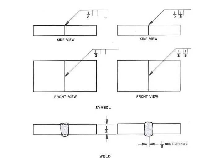
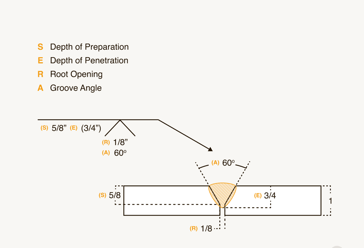
Example 2: V-Groove Weld with Backing
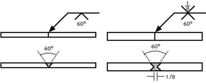
Interpretation: Double V-groove weld with 60° included angle, 1/8 inch root opening, with backing bar on the opposite side. Weld to be ground flush after completion.
Pro Tips for Reading Welding Symbols
1. Arrow Side vs. Other Side
Symbols below the reference line apply to the arrow side of the joint. Symbols above apply to the other side.
2. Tail Information
Always check the tail for process specifications (SMAW, GTAW, etc.) or reference documents.
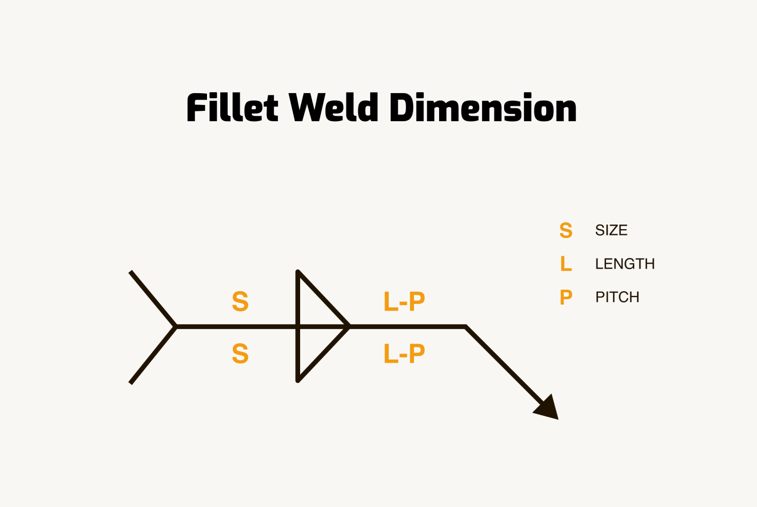
3. Dimension Order
For fillet welds: leg size is first, length is second (if specified). For groove welds: root opening, groove angle, etc.