Practical GD&T Guide
Applying ASME Y14.5 Geometric Dimensioning and Tolerancing
GD&T Fundamentals
Geometric Dimensioning and Tolerancing (GD&T) is a system for defining and communicating engineering tolerances. It uses a symbolic language on engineering drawings and computer-generated 3D solid models to explicitly describe nominal geometry and its allowable variation.
Form Controls
- Straightness
- Flatness
- Circularity
- Cylindricity
Orientation Controls
- Perpendicularity
- Angularity
- Parallelism
Location Controls
- Position
- Concentricity
- Symmetry
Runout Controls
- Circular Runout
- Total Runout
GD&T Symbols Quick Reference
Flatness
Controls the flatness of a surface relative to itself
Circularity
Controls roundness of circular elements
Cylindricity
Controls form of cylindrical surfaces
Perpendicularity
Controls 90° relationships between features
Angularity
Controls specific angle relationships
Parallelism
Controls parallel relationships
Position
Controls location of features
Concentricity
Controls coaxiality of features
Practical Application Examples
Example 1: Bracket Mounting Holes
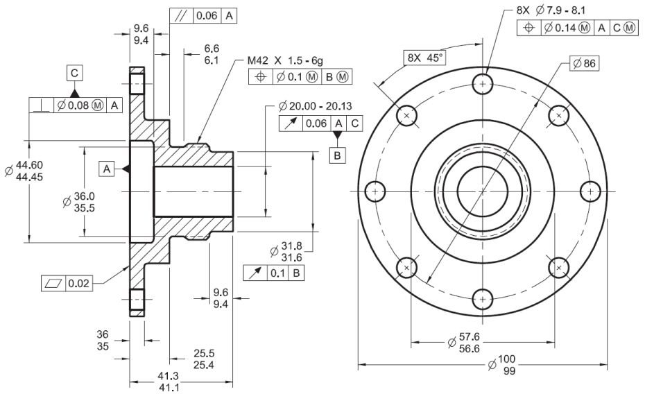
Scenario: Eight mounting holes need to maintain precise location relative to each other and to the mounting surface.
Solution: Use position tolerance with a datum reference frame:
- Primary datum (A): Mounting surface (flatness controlled)
- Secondary datum (B): Edge for orientation
- Tertiary datum (C): Perpendicular edge for complete location
Tolerance: Position Ø0.1 relative to A|B|C
Example 2: Rotating Shaft
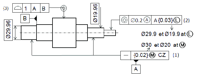
Scenario: Shaft must rotate smoothly in bearings with minimal vibration.
Solution: Combine multiple controls:
- Cylindricity control on bearing surfaces
- Total runout control for entire rotating surface
- Concentricity between bearing surfaces
Tolerances: Cylindricity 0.01, Total Runout 0.02 relative to axis A-B
Pro Tips for Effective GD&T
1. Start with Functional Requirements
Always base your tolerances on how the part functions in its assembly, not just manufacturing capabilities.
2. Use Datums Strategically
Select datums that match assembly interfaces and functional surfaces.
3. Consider MMC/LMC
Apply maximum material condition (MMC) or least material condition (LMC) modifiers when they provide functional benefits.
4. Avoid Over-Tolerancing
Only specify tight tolerances where absolutely necessary to control costs.
5. Combine Controls Wisely
Use form controls for individual features and location controls for feature relationships.
6. Communicate with Manufacturers
Ensure your suppliers understand your GD&T requirements and can measure them properly.