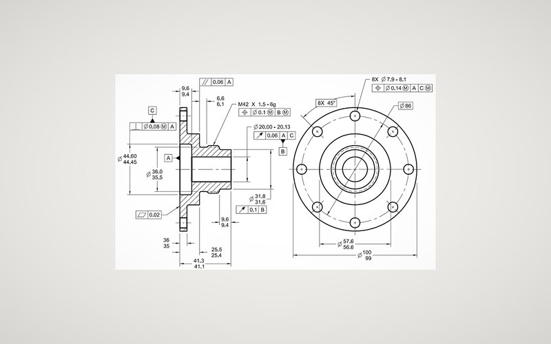
I review a lot of drawings. The single most common thing I find is not an error. It is redundancy — geometric controls that specify something the size limits had already made mandatory.
It is worth being precise about this, because the redundancy is not free. Every unnecessary control is an inspection operation somebody has to perform, a report line somebody has to review, and a rejection somebody has to disposition.
What Rule #1 actually says
For a feature of size — a shaft, a hole, a width — the limits of size control form as well as size. Specifically:
- At maximum material condition, the feature must lie within a boundary of perfect form at MMC. A shaft at its largest allowed diameter must be perfectly straight and perfectly round.
- As the feature departs from MMC, form error is permitted up to the amount of that departure.
So a Ø20.00 / Ø19.90 shaft made at Ø20.00 must be perfect. Made at Ø19.90 it may have up to 0.10 of form error, because the envelope still contains it.
That is not a technicality. It is a complete form control, applied automatically, at no cost, on every feature of size on the drawing.
Which means these are usually redundant
Add a flatness callout to a plate whose thickness is already toleranced, and ask yourself what it is buying. If the flatness value is larger than the size tolerance, it controls nothing — the envelope was tighter. If it is the same, it is a restatement. Only if it is smaller has it added a requirement, and then you should be able to say what function needs it.
The same test applies to straightness on a shaft, and to circularity on a turned diameter. Ask three questions:
- Is this tighter than the size tolerance already forces?
- If yes, what function requires it?
- If I cannot name the function, why is it on the drawing?
I have never had question 3 go well for the drawing.
When you genuinely do need them
There are real cases, and they are worth knowing so you can spot the difference:
- Straightness applied to a derived median line (the callout sits with the diameter dimension, with a Ø modifier). This is a different control entirely. It overrides Rule #1 and permits the feature to violate the perfect-form envelope. Used deliberately on long shafts where a slight bow is acceptable and the perfect-form boundary would be unreasonably expensive to hold.
- Flatness on a surface that is not a feature of size — a single face, a mounting pad, a gasket seat. Rule #1 has nothing to say here, because there are no opposed elements. If it matters, you must control it.
- Anything with the Ⓘ independency modifier, which switches Rule #1 off on purpose and requires you to control form separately.
- Cylindricity, which controls circularity, straightness and taper together and is genuinely tighter than the envelope in many cases. It is also expensive to inspect, so specify it when the function needs it and not as a reflex.
The cost of specifying it twice
The inspection plan is written from the drawing. Every feature control frame becomes a measurement. On a CMM that is programming time and cycle time; on circularity or cylindricity it may mean a dedicated roundness instrument and a separate setup.
Worse, a redundant control creates a rejection path with no functional meaning. A part comes back out of tolerance on a flatness callout nobody needed, and now somebody senior is spending an afternoon writing a concession for a part that would have worked perfectly.
I would rather spend that afternoon on the tolerance that was actually load bearing.
The habit worth building
Before adding a geometric control, say out loud what it prevents. Not what it controls — what it prevents. "This stops the flange face rocking on the gasket." "This keeps the bore from bell-mouthing where the bearing sits."
If the sentence comes easily, the control belongs on the drawing. If you find yourself saying "well, it should be flat," the size limits have already handled it, and you are about to make the part more expensive for nothing.
And the one nobody adds
While we are here: the control that is missing far more often than any of these is the diameter modifier on position, and the Ⓜ that goes with it.
Position at MMC on a clearance hole releases bonus tolerance as the hole grows away from MMC. On a typical bolted flange that is frequently a third more usable tolerance than the frame appears to allow — free, with no effect on function, because the assembly condition is unchanged.
Leaving it off is a decision to make the part harder to produce than it needs to be. It is the exact mirror image of the redundant flatness callout: one adds cost by controlling what did not matter, the other adds cost by refusing tolerance that was already available.
Both come from the same place, which is specifying by habit rather than by function. The fix for both is the same sentence: what does this prevent?
There is a full GD&T reference with a frame builder on the bench if you want the fourteen characteristics side by side.